For the past weeks in this module I have learned a lot more about MAX MSP and feel that this can be a useful tool for my further studies or even professionally. Reflecting back at my project, I am really happy how it turned out especially after days of frustration in getting the RFID Reader to work. Also getting MAX MSP to do what I want, all in all it has taught me a lot more about efficient researching.
We have seen some interesting concepts during the presentations with different implications; social, political etc. It was good to see what other students had done and how they had progressed their ideas over the past few weeks.
Before the presentation, when I had set up my project a lot of people played with it and the random combinations of the adjectives and nouns resulted in some hilarious combinations.
I would like to believe that my presentation was satisfactory and I was able to demonstrate exactly what I planned to create for Assignment 3. Most importantly I succeeded in creating a fun Digital Arts object, which I would try myself if I would find it exhibited in a gallery. As mentioned in my presentation this project is not just limited to an RFID reader you could also place it somewhere near a door with a sensor, so when people walk through the door it will play random words.
I think the Arduino has really pushed everyone to test out some things or look at certain aspects of their project in a different light, since this was completely new to everyone and everyone had to work hard to figure out how to make it work. In the process developing their ideas and making them better along the way. That is certainly how it worked for me, researching for code brought me new ideas because I discovered new options and possibilities of what I could incorporate in to my project.
Still I would like to recommend for someone to have a look at the earlier mentioned BugLabs Systems in my blog. This seems very interesting and maybe easier to get into then the Arduino.
Guido de Koning
20220908
DfIM
Wednesday, 21 January 2009
Monday, 19 January 2009
MAX MSP Final Code
I have been able to get the MAX MSP patch fully working now. With Card ID 1 it will choose randomly from 5 adjectives and with Card ID 2 it will choose randomly from 5 nouns.
I have incorporated a delay into the patch so that if a card is swiped it will just play the word once before another word of the same category is played again. This to prevent a word being activated 5 times in 1 second.

I have incorporated a delay into the patch so that if a card is swiped it will just play the word once before another word of the same category is played again. This to prevent a word being activated 5 times in 1 second.

Friday, 16 January 2009
WAV Audio files
I am having some problems with MAX MSP, because it does not allow me to load WAV files automatically when a patch is opened. It seems only possible when you buy a WAVES plugin for MAX MSP.
So now I will just limit my project to 5 adjectives and 5 nouns to make sure that I have enough time to load each audio file manually.
So now I will just limit my project to 5 adjectives and 5 nouns to make sure that I have enough time to load each audio file manually.
Thursday, 15 January 2009
MAX MSP
I have been playing around in MAX MSP and I succeeded in being able to trigger different words linked to the ID numbers of the different RFID enabled cards.
See MAX MSP code below,

As you can see in the screenshot above the cards will trigger four different words,
This Is Experimental Media
With these four words you could also reconstruct the sentence in to something different,
Is This Experimental Media
Media Is Experimental
Is Media Experimental
This Media Is Experimental
Is This Media
Saturday, 10 January 2009
Text to Speech engine
I have found a website where you can convert Text to Speech for free. Which I will use for my project. They have different voices, male and female also in different accents.
http://www.research.att.com/~ttsweb/tts/demo.php
http://www.research.att.com/~ttsweb/tts/demo.php
Tuesday, 6 January 2009
Project Ideas v2.0
I still want to build on my original concept of being able to activate words via a RFID enabled card. I had an idea as well where I would be able to construct a sentence with a few words or try to construct different sentences with the same words.
Friday, 2 January 2009
Second part of the first Semester
We have had our Christmas break now and I am starting now on the final phases of my project to finalise it. So that I can present my project fully working in Week 8.
I aim to get it fully working, because I feel confident that I will be able to do that. As for my concept I do want to slightly change this and make it more interactive.
I want it to be a fun interactive project where people will feel encouraged to participate in the interactivity. The reason being is that when I visit a gallery I also want to be able to participate in some of the works or able to play with it. Kinetika always has some interesting stuff on display and sometime you are also able to play with these projects, making the overall experience a lot more interesting.
I think that is a great advantage in Digital Arts, a lot of the time people are encouraged not just to think of the social or political implications of a piece, but also to get more intimate with it themselves.
Sunday, 30 November 2008


Types of RFID tags
Active RFID tags
Active RFID tags have a power source, for example a battery, to power them in enable to exchange information with the RFID reader.
Passive RFID tags
Passive RFID tags do not require a internal power source. Instead the RF (Radio Frequency Signal) transmitted by the RFID reader powers up the RFID tag through modulation and demodulation (AC to DC) in enable to exchange information with the RFID reader.
This type of RFID tag is commonly found in,
- Key fobs;
- Credit Cards;
- Oyster Cards;
- Etc.
RFID Hacked
Being able to do a lot of positive and handy things with RFID technology there are also still a lot of security and private issues. Especially since RFIDs can now even be found in passports, credit cards and public travel.
Doing a quick Google brought up a lot of interesting articles of people who were able to hack RFIDs,
Oyster Cards vulnerable to RFID hack, lots of other systems too
U.S. Passport RFID Already Hacked
RFID credit cards easily hacked with $8 reader
How to Hack the RFID Passport Chip
Hackers Clone E-Passports
Steal Credit Card Numbers Wireless using RFID
RFID Technology
RFID is an automated identification method that stands for Radio-frequency identification. It is used quite intensively now a day, probably more than people think.
I have listed a couple of examples below,


I have listed a couple of examples below,


Reflection
Looking at the current research that I have done and my proposals. I want to try and develop a prototype for the third project idea entitled RFID Profile Scanner.
I will now focus my research more on,
- RFID technology
- Arduino
- Tinker.it RFID Module
- MAX / MSP
I will now focus my research more on,
- RFID technology
- Arduino
- Tinker.it RFID Module
- MAX / MSP
Tuesday, 25 November 2008
Musical Robots
At Georgia Tech The Robotic Musicianship Group have developed two robots who are able to "listen" to the music that is being played by other people and they then try to "blend in" trying to match the rhythm and melody.
As Professor Gil Weinberg explains,
Source
Reflection
This is the first time I have ever seen a project like this. The "magic" behind it seems to be a algorithm, but they mention a genetic algorithm which is used to,
Source
I would not want to go into what the usefulness of having a robot play a musical part, but looking at the larger scale where this particular algorithm is able to find a solution very quickly is quite interesting and being able to distinguish these melodies from different melodies.
I remember seeing another application of the last mentioned where 5 Japanese students would simultaneously shout a order at a computer and the computer was able to distinguish all of there orders.
As Professor Gil Weinberg explains,
"The processing allows [the robots] to analyze and improvise," said Weinberg via telephone. "In one of the applications, we use a genetic algorithm... You have a population of something, and then you do mutations to all of these little things -- in my case it's musical motifs -- mutations and cross-breeding between the musical genes, in our case, and then you have a new population that better fits to the environment.
He continued, "Very fast, it runs [about] 50 generations of mutations that are cross-bred between the genes and tests whether this is similar to a motif that the saxophone player played, for example. And it plays something back that is a combination of musical genes of what the saxophone player played, what the piano player played -- something that is unique that only can be the product of genetic algorithm."
Source
Reflection
This is the first time I have ever seen a project like this. The "magic" behind it seems to be a algorithm, but they mention a genetic algorithm which is used to,
Genetic algorithms attempt to find solutions to problems by mimicking biological evolutionary processes, with a cycle of random mutations yielding successive generations of "solutions". Thus, they emulate reproduction and "survival of the fittest". In genetic programming, this approach is extended to algorithms, by regarding the algorithm itself as a "solution" to a problem.
Source
I would not want to go into what the usefulness of having a robot play a musical part, but looking at the larger scale where this particular algorithm is able to find a solution very quickly is quite interesting and being able to distinguish these melodies from different melodies.
I remember seeing another application of the last mentioned where 5 Japanese students would simultaneously shout a order at a computer and the computer was able to distinguish all of there orders.
Sunday, 23 November 2008
Bug Labs
When researching a couple of times I saw the company name Bug Labs dropped in some posts. When doing a quick Google for Bug Labs I ended up on their main site.
It seems Bug Labs might be the next gen Arduino platform.
What or Who is Bug Labs ?
Bug Labs is a new technology company that wants to encourage new wannabe engineers. It is a easy start up platform since it does not require any soldering and you do not have to learn anything about solid state electronics.
Products

Bug Base


Code
A lot of the coding is done in Java which is good news for a lot of people out there so you do not have to learn a whole new language or a language that has been slightly adjusted with some differences here and there.
Example
Here is some example code from a GPS Logger that was made. This piece of code is used to match the long and latitude to match a Google map tile.
Code Source
As with the Arduino Bug Labs also has an entire community available and a good system where user programs our posted with the option to download earlier versions. Everything is open source and all the codes are very well commented.
Reflection
There are some really interesting projects here and the modules look great to play with as well. Although the pricing of the units is a lot higher then what you would spend on the Arduino. Even so it seems well worth it, to bad its our last year here otherwise we might have been able to persuade TVU to give this a go for next year.
Bug Labs
It seems Bug Labs might be the next gen Arduino platform.
What or Who is Bug Labs ?
Bug Labs is a new technology company that wants to encourage new wannabe engineers. It is a easy start up platform since it does not require any soldering and you do not have to learn anything about solid state electronics.
Products
Bug Base
The BUGbase ‘Hiro P’ Edition is the “anchor” of the BUG ecosystem. Each BUGbase is a fully programmable computer, with a CPU, RAM, rechargeable lithium-ion battery, USB, Ethernet, MMC and serial interfaces, and a small LCD with button controls. BUGbase also has 4 slots in which any combination of BUGmodules may be inserted.
BUGview is a 2.46” 320×240 LCD screen which can be used as a touch-sensitive interface. This useful BUGmodule can be used both as a display and as an input device.
BUGmotion is a module with two components: a motion detector and an accelerometer. The motion detector has a range of up to 2m, and detects as little as 30cm of motion. The accelerometer has scalable sensitivity between 2.5g and 10g.
BUGlocate provides GPS receiver capabilities to the BUGbase. It has a passive internal antenna and includes a connector for an external active antenna. BUGlocate uses an SiRF chipset based implementation.
BUGcam2MP is a 2 megapixel digital camera module with a built-in flash.
Code
A lot of the coding is done in Java which is good news for a lot of people out there so you do not have to learn a whole new language or a language that has been slightly adjusted with some differences here and there.
Example
Here is some example code from a GPS Logger that was made. This piece of code is used to match the long and latitude to match a Google map tile.
package gpslogger;
import java.awt.Point;
/**
* GoogleTile.java - describes a Google Tile object that represents a 256x256 pixel
* chunk of the earth's surface.
*
* @author Sean Hill
* @author Dave Sant
*/
public class GoogleTile {
// The point (x,y) for this tile
private Point p;
// The coord (lat,lon) that was used to create this tile
private Point2D co;
// Zoom level for this tile
private int z;
// ...Constants...
private double PI = 3.1415926535;
private int tileSize = 256;
private float pixelsPerLonDegree[] = new float[18];
private float pixelsPerLonRadian[] = new float[18];
private int numTiles[] = new int[18];
private Point2D bitmapOrigo[] = new Point2D.Double[18];
// Note: These variable names are based on the variables names found in the
// Google maps.*.js code.
private int c = 256;
private double bc;
private double Wa;
// Fill in the constants array
private void fillInConstants() {
this.bc = 2*this.PI;
this.Wa = this.PI/180;
for(int d = 17; d >= 0; --d) {
float f1 = (this.c / 360f);
this.pixelsPerLonDegree[d] = f1;
this.pixelsPerLonRadian[d]=(float) (this.c / this.bc);
int e = this.c / 2;
this.bitmapOrigo[d] = new Point2D.Double(e,e);
this.numTiles[d] = (this.c / 256);
this.c *= 2;
}
}
public GoogleTile(double latitude, double longitude, int zoomLevel) {
this.fillInConstants();
this.z = zoomLevel;
this.p = this.getTileCoordinate(latitude, longitude, zoomLevel);
this.co = new Point2D.Double(latitude, longitude);
}
public Point getTileCoord() {
return this.p;
}
public Point2D getTileLatLong() {
return this.co;
}
private Point2D getBitmapCoordinate(double a, double b, int c) {
Point2D d = new Point2D.Double(0,0);
double thispplon = this.pixelsPerLonDegree[c];
Point2D sp = this.bitmapOrigo[c];
int newX = (int) Math.floor(sp.getX() + (b * thispplon));
double e = Math.sin(a * this.Wa);
if(e > 0.9999) {
e = 0.9999;
}
if(e < -0.9999) {
e = -0.9999;
}
double thispplonrad = this.pixelsPerLonRadian[c];
int newY = (int) Math.floor(sp.getY() + 0.5 * Math.log((1 + e) / (1 - e)) * -1*(thispplonrad));
d.setLocation(newX, newY);
return d;
}
private Point getTileCoordinate(double a, double b, int c) {
Point2D d = this.getBitmapCoordinate(a, b, c);
Point e = new Point((int)(Math.floor(d.getX() / this.tileSize)),(int)(Math.floor(d.getY() / this.tileSize)));
return e;
}
public int getZoom() {
return this.z;
}
}
Code Source
As with the Arduino Bug Labs also has an entire community available and a good system where user programs our posted with the option to download earlier versions. Everything is open source and all the codes are very well commented.
Reflection
There are some really interesting projects here and the modules look great to play with as well. Although the pricing of the units is a lot higher then what you would spend on the Arduino. Even so it seems well worth it, to bad its our last year here otherwise we might have been able to persuade TVU to give this a go for next year.
Bug Labs
POV display
This huge POV display was created by Mario Mauerer and a couple of his friends. It uses a total of 100 blue SMD LEDs to display the images.

The machine needs to get at least at a speed of 600 RPM to generate a image withouth any flicker disturbing the image.
The machine needs to get at least at a speed of 600 RPM to generate a image withouth any flicker disturbing the image.
Applause Machine
The designer of the applause machine is a British artist called Martin Smith of Laikingland. He designed this machine “for when your ideas are great but no one else agrees.”


Source
Laikingland is a creative collaboration based in both the UK and The Netherlands. We design and manufacture beautifully crafted kinetic objects. Our first product the Applause Machine is designed by British artist Martin Smith. Just press the button and the Applause Machine enthusiastically claps its hands for you.
Source
Saturday, 15 November 2008
Arduino Gameboy
I just wanted to post this to show how powerful the Arduino actually is. I mean what can it not do ? I found this project where someone had converted his Arduino with some add-ons to his own hand held console.

This shows again how much possibilities the Arduino gives to create whatever you want. Your imagination seems to be the limit here.
Source

This shows again how much possibilities the Arduino gives to create whatever you want. Your imagination seems to be the limit here.
Matt over at Liquidware decided to build an “open source Gameboy” (known as the Gamepack) using off-the-shelf parts, including the modder-friendly Arduino microprocessor. While the Arduino may provide the brains of the operation, the 128×128 TouchShield Stealth color OLED touchscreen is most definitely the soul. Rounding out the build is an Inputshield board, which provides a tiny joystick (complete with rumble) and control buttons as well as a flat Lithium battery pack.
Source
Monday, 10 November 2008
Project Idea 3.0 : RFID Profile Scanner
A took the RFID kit home from a previous lesson, but failed to find a good purpose for it that did not seem too obvious.
Now I have come up with an idea that will allow me to use two project ideas in one. Namely combining the wall light sensor with the RFID scanner.
Imagine a house where each and every door opening has a RFID antenna. Whenever a person walks through a door the person gets scanned to see if he has any RFID chip on him.
These chips can be carried and implemented in numerous ways,
- Clothing
- Card
- ID Tag
- Implemented under the skin (extreme solution)
- Rings, Watch etc.
As soon as the RFID profile has been read from the chip the light in the room will be adjusted to the users preferences. Obviously you do not always want the light to be the same all the day if you are in the room. Here is where the Wall Light Sensor comes in places from Project Idea 1.0
So I want to combine the two to create one effective and energy efficient why of controlling the lights in your rooms.

Every door opening could have a metallic strip which is the RFID antenna. In the above illustration the metallic strip has been made very visible for illustrational purposes, but this strip can easily be hidden in the door opening.
Thursday, 6 November 2008
Facial Expressions
I came across this article where robotic engineers used 34 servo motors to mimic facial expressions.
Source
Source
Wednesday, 5 November 2008
Dancing Robot
I have always been interested on seeing how I could use a servo in one of my projects. Whilst researching this I came across this robots which uses a number of servos to "dance"
In one of my other posts as well a servo is used to open a door. At the moment I still like the idea of the touch light on the wall, but am still looking for something else where I could use a servo.
Anyway here is the video,
I tried researching more to see where this robot came from, but the only place where it leads back to is a YouTube page with the following information text,
Which roughly translates into,
After researching some more I ended up with finding the schools website, Höheren Technische Lehranstalt in Austria, and it seems to be a competition they hold each year with a so called "Dancing hexabot" they have a page which highlights the 2007 event but not yet for 2008,
HTL - Hexarobot
Conclusion
Definitely interesting to see how they use these servos to create a "Dancing Hexarobot" more interestingly for me is how they would get the servos to synchronise so perfectly and execute these quite sophisticated movements.
This definitely gave me more inspiration into finding a good use for a Servo based project, but still I have been unable to come up with a strong idea.
In one of my other posts as well a servo is used to open a door. At the moment I still like the idea of the touch light on the wall, but am still looking for something else where I could use a servo.
Anyway here is the video,
I tried researching more to see where this robot came from, but the only place where it leads back to is a YouTube page with the following information text,
Schüler der HTL-Saalfelden siegte auf der Österreicheschen Meisterschaft!!!
Which roughly translates into,
Student of HTL steals the show at the Austrian championships.
After researching some more I ended up with finding the schools website, Höheren Technische Lehranstalt in Austria, and it seems to be a competition they hold each year with a so called "Dancing hexabot" they have a page which highlights the 2007 event but not yet for 2008,
HTL - Hexarobot
Conclusion
Definitely interesting to see how they use these servos to create a "Dancing Hexarobot" more interestingly for me is how they would get the servos to synchronise so perfectly and execute these quite sophisticated movements.
This definitely gave me more inspiration into finding a good use for a Servo based project, but still I have been unable to come up with a strong idea.
Sunday, 2 November 2008
Project Idea 2.0 : Fridge Management System
In the light of the two previous posts, reminding yourself of something you always forget and having something handy to help you out with a boring household chore.
I came up with the idea of a Fridge Management System. We have all heard of those automated fridges of the future which order your shopping and even tell you which products are running low.
But is it a advantage having everything completely automated where the fridge even tells you if a product is about to finish and orders automatically a new one... ?
Do you even want a new one ? or was it just a one-off buy ? You do not want your fridge to re-order a £1000 canister of caviar automatically.. do you ?
How annoying is it going to be if the fridge notifies you whenever something is almost empty ? people have way too many miscellaneous things in their fridge for this to be a fully working automated system. As mentioned before a person would have to be very precise and systematic in what he or she stores in their fridge for the fridge to be able to differentiate what exactly is needed.

I think automating orders for products like this will never be fully functional in the way you want it to be. There are too many variables in play for this to be a full proof system. It could probably only work well if the shopper itself is very consistent in its shopping and does everything as the system requires him to do.
An advantage of this is that you could implant a intelligent comparison system that could offer you alternatives that might be available at other supermarkets or let you know if a particular supermarket has a offer on that item.
Advanced Fridge
Whilst doing research a stumbled on this fridge from LG that seems to have everything that you would need for a fridge and more.

It has a,
- LCD Screen
- DVD
- Wi-Fi
- FM Radio
- Ability to look up recipes
- Digital Photo album
- Etc.
Conclusion
The reason why I posted this advanced fridge is that it interests me what other functions you can add to a fridge to make life easier. Especially the recipe book strikes me as a brilliant idea.
Which housewife is never short of ideas of what to cook ? having a digital recipe book with probably the ability to store an infinite number of recipes seems like a very handy feature. Also because is fridge is usually 99% of the time located in the kitchen which makes it easily accessible.
Same for the radio and the LCD Screen it provides a lot of entertainment whilst cooking.
Source
Wednesday, 29 October 2008
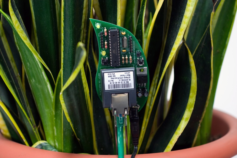
Plant Lets You Know When Its Thirsty
Here a moist sensor is used to measure if the plants needs to be watered or not. If this is the case the Arduino communicates with twitter and lets the user know, wherever he is, that his plant needs to be watered.


Reflection
Very interesting way of using the web 2.0 to get information across. I would say its a very practical solution if you are one of those persons who is always on the net but forget the choirs that need to be done around the house. A perfect way to remind yourself what needs to be done.
Source
Botanicalls Kits let plants reach out for human help! They offer a connection to your leafy pal via online Twitter status updates to your mobile phone. When your plant needs water, it will post to let you know, and send its thanks when you show it love.

Reflection
Very interesting way of using the web 2.0 to get information across. I would say its a very practical solution if you are one of those persons who is always on the net but forget the choirs that need to be done around the house. A perfect way to remind yourself what needs to be done.
Source
Tuesday, 28 October 2008
DIY Gmail Notifier
I actually also researched in this particular idea last year when we had Maverick Machines. It took my interest then that we could use the Arduino to present a more physical way of grabbing someone's attention.

Again in this project a Arduino is used or rather a Boarduino. Probarly the main important thing here is the code that drives this project to turn the light to a specific colour. The hardware set-up itself is not something very complicated that we have not seen before.
I was however intrigued by using a different language to drive the Arduino the code seems pretty straightforward and gives some more insight on how to read the USB Serial port as well.
The above code is Python script which is used in combination with the Universal Feed Parser module from feedparser.org
Source

The following guide is deliberately fairly high-level, because the exact details will vary depending on your operating system and particular hardware setup. I did this with my Mac, but hopefully there'll be enough information here for you make it work on your system, perhaps with a little Googling.
If you don't happen to have a glowing cube lying around, you can modify this to work with almost any output device you could think of, from a simple LED, or a buzzer, to something far more clever like moving a servo (Gmail Notifier Robot, anyone?)
Again in this project a Arduino is used or rather a Boarduino. Probarly the main important thing here is the code that drives this project to turn the light to a specific colour. The hardware set-up itself is not something very complicated that we have not seen before.
I was however intrigued by using a different language to drive the Arduino the code seems pretty straightforward and gives some more insight on how to read the USB Serial port as well.
1. import serial, sys, feedparser
2.
3. #Settings - Change these to match your account details
USERNAME="username@gmail.com"
PASSWORD="yourpassword"
4. PROTO="https://"
SERVER="mail.google.com"
PATH="/gmail/feed/atom"
5.
6. SERIALPORT = "/dev/tty.usbserial-FTDK0P3M" # Change this to your serial port!
7.
8. # Set up serial port
9. try:
10. ser = serial.Serial(SERIALPORT, 9600)
11. except serial.SerialException:
12. sys.exit()
13.
14. newmails = int(feedparser.parse(PROTO + USERNAME + ":" + PASSWORD + "@" + SERVER + PATH)["feed"]["fullcount"])
15.
16. # Output data to serial port
17. if newmails > 0: ser.write('M')
18. else: ser.write('N')
19.
20. # Close serial port
21. ser.close()
The above code is Python script which is used in combination with the Universal Feed Parser module from feedparser.org
Source
Saturday, 25 October 2008
Project Idea: Wall Light Sensor
I came up with this idea when I was researching the article below, DIY Magic Mirror, the idea is basically that instead of a light switch you have a marked area on the wall with a touch sensor behind it which will act as your light switch.
The Arduino will serve as a medium to interpret touch. A short touch to the area could function as the on and off command. Touching the upper area will increase the brightness of the light and touching the lower side of the touch area will decrease the brightness of the light in the room.
Here is a little mock-up of how this could look,

Conclusion
I see this as an actual feasible fully working idea. I have almost all the necessary experience to realise this project. The only part that is unfamiliar with me is using a actual light that is connected to 220v.
Although instead of using live wires I could just use a LED which would demonstrate the same principle anyway.
Thursday, 23 October 2008
DIY Magic Mirror
I came across this project from a man who wanted to create a magic mirror as found in Disney World for his daughters. He uses a interesting mixture of sensors in this project. I am particularly interested in the touch sensors he is using behind the wall.
The light sensors is something we have used ourselves before in one of our projects from last year so that is not something new really.
Reflection
As mentioned before I was very interested in the type of sensors used in the project especially the ones behind the wall. I could think of some interesting things to use here such as a light switch without a switch.
Source
After multiple trips to Disneyland, I got the idea to do a Snow White type magic mirror for my two girls. I found a product after some googling but it was quite expensive so I decided to build my own. While at it, I figured I better add a Halloween Mode and Pirate mode.
The light sensors is something we have used ourselves before in one of our projects from last year so that is not something new really.
Reflection
As mentioned before I was very interested in the type of sensors used in the project especially the ones behind the wall. I could think of some interesting things to use here such as a light switch without a switch.
Source
Monday, 20 October 2008
Keyless Entry System
A student was looking for a innovative way to open his door without the need for keys. He combined a touch sensor with a high powered servo all controlled by an Arduino to open his door.
Whilst touching the sensor with his fingers in a specific manner, his code, the servo gets activated and opens the door.
Below is a little video of the system in action,
Reflection
A interesting use of technology here, not too complex and to be easily executed. It would be interesting to see this concept fully integrated in a door.
With the actual door knob being the sensor, as mentioned in the article it says that the door knob seemed a too big of a surface area to get accurate responses. Although you could have a plastic doorknob with just a small patch of where the sensor is.
Having the servo fully integrated in the door and this would be quite a innovative way of opening your door opposing technological solutions as keypads and fobs.
Source
Experimental Media
Introduction
In this particular blog i will keep track of my research and project ideas I might have for the next assignment.
In my research I will be mainly looking at innivative solutions to common problems of every day to day life or interesting future technologies.
For my own project I will be interested in creating a innovative solution myself for a common every day problem or a improved solution to existing technology.
Guido de Koning
20220908
Subscribe to:
Comments (Atom)